Tuesday, April 25, 2017

Inverting Differentiator

In this lab, we are going to make Inverting differentiator and input sin wave in input voltage. We are going to calculate the estimated output voltage and finally, we are going to measure the output voltage at different frequency sin waves(at same amplitude).
We first calculated output voltage as a function of input voltage and time.

We calculated at what frequency we have gain of 1(V_o=V_in). We found that happens when the frequency is 234 Hz.
Setup(1)
Setup(2)
Setup(3)
We measured actual Capacitance and Resistance, it is 0.945 μF and 668-ohm respectively.


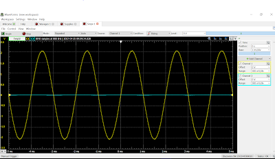
We measured output voltage at 500Hz, 250Hz, and 100Hz.
100Hz 1V

250Hz 1V

500Hz 1v
At the end, we calculated theoretical V_out and compared with the measured value. It has very small percentage of difference.
Summary: This lab went great, we got our estimated value. we calculated the circuit will have gain of 1 at 234Hz and we got gain of 1.1 at 250 Hz, so we would get value very close to 1 when we input 234Hz sin wave. We have higher gain in higher frequency because when we differentiate input voltage the angular velocity-omega will go out and multiply with amplitude due to chain rule. Omega can be also expressed as 2fπ, f stands for frequency.

Tuesday, April 18, 2017

Passive RC Circuit Natural Response

This morning I went to wake up my dog.
Start of this class we did some problems related to RC and RL circuits...

Problem(1)

Problem(2)
Starting Lab...

We first calculated the voltage across capacitor when it is fully charged and the times it takes to discharge 99% of charge.(It happens when time elapsed 5 times of time constant(tau). It was 0.0756 second. The actual resistance for 1k-ohm was .95k-ohm and 2.2k-ohm was 2.13k-ohm
We used Triggering and Single Acquisition feature from Appendix.
Discharge time we have got from two data point was -22.17ms(initial) and 118.6ms(Final).

Charge time we got from two data point was -5.13ms(initial) and 105.1ms(final), and max voltage was 3.48V which is very close to what we expected.
Summary:we calculated it will take 0.0756 second to fully discharge the capacitor, however, experimental value says it will take 0.14 second to discharge, twice of what we calculated. So there is mistake in our calculation or lab procedure. For time for it to charge, it was 0.11 second, but we did not calculate the times for circuit to fully charge itself.(we forgot and we thought we don't need it). We got our maximum voltage for capacitor correct, which we calculated to be 3.43V and measured amplitude is 3.48V.

Saturday, April 15, 2017

Inductor Voltage-current Relations

Starting lab...
                 This lab is almost same with previous lab "Capacitor Voltage-current Relations", but we change capacitor with inductor and measure same thing in 3 voltage sources.
1kHz, 2V Sinusoidal input Voltage

2kHz, 2V Sinusoidal input voltage

100Hz, 4V triangular input voltage
Summary: It makes sense that all of voltage across inductor is very low because inductors resist change in voltage. So Voltage across them are low compare to input voltage. This lab I think we also messed up the input equation of current, or it might be very low. As for voltage in triangle wave, I think because the amplitude of wave is high again, so inductor want to resist its high slope of change and thus have very low voltage across it.

Capacitor Voltage-current Relations

First, we did some problems


Starting lab...
                In this lab, we are going to connect a resistor(100-ohm) and capacitor in series with sinusoidal voltage sources and triangle source and we are going to measure voltages across resistor and capacitor.
(Notes: sinusoidal voltage source can go through capacitors)
Setup(1)

Setup(2)

Graph of sinusoidal wave with 1kHz and 2V amplitude

Graph of sinusoidal wave with 2kHz 2V amplitude

Graph of triangle wave with 100Hz and amplitude of 4V
 Summary: In this lab we used both sinusoidal and triangle wave through circuit with resistor and capacitor in series. With its frequency increased in second measurement it is appeared that voltage difference between resistor and capacitor is decreased. It could be case of with frequency changing so fast that capacitor does not have enough time to charge to higher voltage. As for triangle wave, we could see it stops charging at certain times; it is because the amplitude of triangle wave is twice of voltage as before so the capacitors charge to its charging capacity and thus stop charging. For the curve of current(orange line), I think you typed the equation wrong in waveform or it could be very small ,so we could not see it is actually changing.

Tuesday, April 11, 2017

Temperature Measurement System Design


We first started the day with a problem(Op amp on an Op amp!!!)
Starting Lab...

The philosophy of this lab is to use thermistor in same way as in the previous lab "Temperature Measurement System" to obtain desired voltage difference of hot temperature of thermistor and cold temperature. In "Temperature Measurement System", we got voltage difference of 0.5V, but in this lab, we desire 2V of difference, so we are going to connect terminals at where we measure voltage difference into terminal of operational amplifier.
We first did thing called "balancing the bridge". We are using potentiometer as one of resistor to bring voltage across two points we want measure to zero.

Close-up setup(1)

Close-up setup(2)
We assumed difference of voltage across two terminal when it is cold(20 C) and hot (37C) was 0.5V, and using that to calculation we decided we need to amplify the output voltage 4 times to reach 2V(4*0,5=2V). We choose 3K and 12K-ohm resistor as our resistors.(Actual resistances are also labeled)
(There should be a video here but I cannot move it to here, it is at the very front of this blog, Caption of the video is here.) 
(Caption: In this video we would get output voltages of 1V because actual voltage difference across the bridge we constructed without amplification was 0.25, so with amplification of 4, we got output voltage of 1V)

Summary: The mistake of this lab was we just assumed that output voltage without amplification was 0.5V (but really it was 0.25V), so with amplification of 4, we got our measurement of about 1V. We should have measured voltage difference without amplification and then choose proper resistors to amplify the input voltages(we should have choose resistors with 8 times differences).


Thursday, April 6, 2017

Difference Amplifier


 Starting Lab....
In this lab, we are looking for a setup will take difeerence between two voltage source and either keep it as it was or multiply it as our output Voltage.

We did some calculation first to figure out what resistance we need to choose to achieve twice of difference of two voltage source (At end of calculation, I wrote R1=R2 but it can be ignored(wrong)), and we found out we need to choose a reisstor that will have relationship same as 2R_1=R_2, 2R_3=R_4.

We set it up(we did not take picture of circuit) and measured output Voltages.
We actually use negative of our result to plot and I will explain it in Summary.
Summary: So we did all that and measured output Voltage. Relationship of V_out and V_a and V_b is V_out=2(V_b-V_a), but we found out our result is negative of what we expected. So we figured out we must have our V_a and V_b swaped and cause negative output value. Than we have very similar expected and measured output Voltage.

Summing Amplifier

At the start of class we did some problems
We did some practice problems

We did additional problems

 Starting lab....
In this lab we analyzed  summing of two voltage source will be amplified, basically, we are setting up a circuit that will sum the voltage of two sources and if we adjust as we desire, we can amplify those voltages.


Setup(1)

Setup(2)

Setup(3)

This is V_out for 1V and 2V sources, together they will have -(2+1)=-3 V

We recorded actual resistance (The calculation we showed at left uses 1.3K-ohm as a resistor but in lab we used 2.2K-ohm resistor as our resistor.

Our result
Summary: In our result, we did get really similar to what we expected, with just minor difference. It is very likely to cause by actual resistance of resistors. We got negative number of sum of voltages. Additionally, the voltage is saturated at -3.35 Volt but we did not get upper limit saturation.


Tuesday, April 4, 2017

Inverting Voltage Amplifier

In this class meeting, we learned about operational amplifiers...

We did some problems first (1)

We did some problems first(2)


We did additional problems (we got 0 as answer when the correct answer was 9 V, we used 2000 as our open loop voltage gain when it was actually 2*10^5.)

Starting the lab...
The setup(1) We choose 4.7k-ohm and 2.2k-ohm resistors.
The setup(2)
The setup(3)
The setup (4)
We measured actual resistance of resistors and output voltage for each input voltage(we did not measure output voltage for negative voltage(we forgot)), and the V_out should have negative relationship with V_in;
Actual resistance for resistors were 4.67k for 4.7k-ohm resistor and 2.16k for 2.2k-ohm resistor(wrote vertically)
.
V_in V_out Expected V_out
0 0 0
0.5 1.07 1.081018519
0.75 1.61 1.621527778
1 2.15 2.162037037
1.25 2.69 2.702546296
1.5 3.23 3.243055556
1.75 3.46 3.783564815
2 3.45 4.324074074
2.5 3.45 5.405092593
3 3.45 6.486111111

Summary: This lab was easy. We choose 2.2k-ohm and 4.7k-ohm resistor to try to get voltage change to two times as input voltage. The actual resistance of resistor was 2.16k and 4.67k respectively. However we got positive multiplication of V_in, but everybody else in class was talking about they got negative multiplication of V_in. So we must measured V_out with negative terminal of multimeter and connect positive terminal with ground. Also we forgot to measure negative V_in. From the graph and data table, we can clearly see that V_out does not go beyond 3.434V, V_out goes beyond was saturated. However, our positive limit voltage was 5V and negative limit voltage was -5V. Instructor later explained that OP-27 does not bound its V_out to its positive and negative limit voltage, that's why it does not go beyond 3.43V. The V_out smaller than 3.43V was consistent with expected V_out=(V_in *(4.67/2.16)).