Sunday, May 28, 2017

Apparent Power and Power Factor


Introduction: In this lab, we set up the circuit it is given to us and make a minor change of different load resistor and measure its V and I rms.

At first, we calculated various data that was required

The setup.
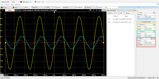
With 10-ohm resistor, 
With 47-ohm resistor.
With 100-ohm resistor,

Summary: Our calculation was totally off the chart. It is said in the menu that we should use channel 1 to measure the input voltage but we measured voltage across 10-ohm resistor for R_t and used it to measure current and put input in Math channel 1, so we do not think this make much difference. When we were using 10-ohm and 47-ohm resistor in Load impedance, RMS of Voltage and Current did not change much, but when we used 100-ohm resistor, RMS voltage almost halved and current did not change much.

Tuesday, May 16, 2017

Impedance

Introduction: In this lab, we are going to apply voltage with different frequency to RR, RL, and RC circuit to measure current through each circuit.
                 First we calculated expected current in each circuit when amplitude of 2V and 5k frequency for supply voltage.


Expected current in each circuit.
In the following graphs, channel 1 (yellow curve) is voltage across 47-ohm resistor, channel 2(Cyan curve) is either 100-ohm resistor, capacitor, or inductor depends on which circuit, and Channel 3(Orange curve) is current through circuit.
1k frequency, 100-ohm Resistor

5k frequency, 100-ohm Resistor

10k frequency, 100-ohm resistor
With resistor component, voltages and currents are in phase and magnitudes did not change, but periods changed in different frequencies.

1k, Inductor Gain=0.1305, Phase= 278.1°

5k, Inductor, Gain=0.5381, Phase=27.365°
10k, Inductor, Gain= 0.7938, Phase=272.34


1k, Capacitor, Gain=1 Phase=89.424°
5k, Capacitor, Gain=1,Phase= 90.77°
10k, Capacitor, Gain=1, Phase= 86.76°
Summary: In all experiments, current is always in phase with voltage across 47-ohm resistor.
When we connected a resistor in series with circuit, the gain, amplitude did not change and 3 curves were all in phase. When circuit connected with an inductor, the gain increased with frequency and have certain phases. When circuit is connected with a capacitor, the gain was always one and also current increased as frequency increased.

RLC Circuit Response

Calculation

Sunday, May 14, 2017

Phasors: Passive RL Circuit Response

Introduction: In this lab, we calculated current for RL circuit ran with ac current with it's voltage source. After that, we divided function of current with voltage to get gain of the circuit in three different angular momentum. We built the circuit and compared with calculated values.
We calculated gain of circuit when ω is 47k rads per second is 0.015, when it's 4.7k rad/s(ω/10), it's 0.0212, and 0.00212 when its 470k rad/s(10ω).
Unfortunately, we did not take picture of built circuit.

4.7k rad/s, gain of 0.0212 (Brown line) (it's shown it's at 0.212 because we are showing 10 times of measured value using 0.02A/div (Voltages are at 0.202V/div))

47k rad/s, gain of 0.015

470k rad/s, gain of 0.00212
Summary:  This lab gave us our expected values. every gains matched our calculated values. Notable points in this lab were at 4.7k rad/s, V_in and current were inphase, at 47k rad/s, they were all off-phase, and when ω was at 470k rad/s, V_in and V_L were in-phase.