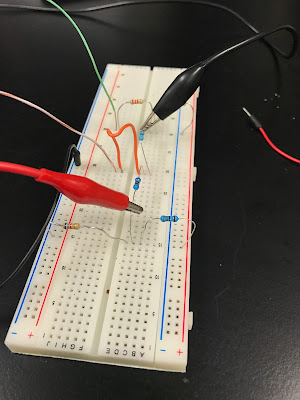
We collected some Voltage and Resistance data and used P=(V^2)/R to get their power and plotted against Voltage. (Graph seems wrong)
Summary: In this lab, we first calculated R_th and V_th of the circuit. and then we choose a resistor bigger than 4k-ohm and smaller than 10k-ohm(we used 4.8k-ohm) to measure its actual Voltage across its terminals, which were very different than V_th we calculated. And at last, we used Potentiometer to vary our resistance and gather some data of Voltage at different resistance and used it and equation P=(V^2)/R to plot Voltage vs. Power graph and tried to find a resistor that gives us maximum power at across terminals. However, we made mistakes and our graph looks very wrong.
|


No comments:
Post a Comment